Posts

Insulation in a Transformer

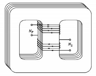
Insulation in a Transformer The insulation is used to prevent the conductors shorting together in a transformer is usually a thin layer of varnish or enamel in air cooled transformers. In larger power and distribution transformers the conductors are insulated from each other using oil impregnated paper or cloth. The whole core and windings is immersed and sealed in a protective tank containing transformer oil. The transformer oil acts as an insulator and also as a coolant.
Why do we need transformers?

A transformer ideally changes one ac voltage level to another voltage level without affecting the actual power supplied. If a transformer steps up the voltage level of a circuit, it must decrease the current to keep the power into the device equal to the power out of it, as per law of conservation of energy. Therefore, ac electric power can be generated at low voltage, its voltage stepped up for transmission over long distances at very low losses, and its voltage stepped down again for final use. Since the transmission losses in the lines of a power system are proportional to the square of the current in the lines, raising the transmission voltage and reducing the resulting in reducing I 2 R loss and increasing power output.

Transformers

Image
Transformers A transformer is a device that changes ac electric power at one voltage level to ac electric power at another volt age level through the action of a magnetic field. It consists of two or more coils of wire wrapped around a common ferromagnetic core. These coils are (usually) not directly connected. The only connection between the coils is the common magnetic flux present within the core. One of the transformer windings is connected to a source of ac electric power, and the second transformer winding supplies electric power to loads. 1 st transformer winding connected to the power source is called the primary winding or input winding, and the winding connected to the loads is called the secondary winding or output winding. If there is a third winding on the transformer, it is called the tertiary winding. So transformer is a static machine which only transfer electric power from one electric circuit to another electric circuit. The frequency in a transforme...

Cogging , Crawling and Skewing

cogging With the number of stator slots equal to or an integral multiple of rotor slots, the variation of reluctance as a function of space will be quite pronounced resulting in strong alignment forces at the instant of starting.  These forces may create an aligning torque stronger than the accelerating torque with consequent failure of the motor to start. This phenomenon is known as cogging. Such combination of stator and rotor slots must, therefore, be avoided in machine design. Crawling The tendancy of the motor to run at a stable speed as low as 1\7 of normal speed synchronous speed and being unable to pick up its normal speed. A 3 phase winding carrying sinusoidal currents produces space harmonics of the order       Belt harmonic               =              h= 6k±1 where k is positive integer 1,2,3,… when k is ...

Single Phase Induction Motor

Image
Single phase induction motor A single-phase induction motor comprises a single-phase distributed winding on the stator and cage winding on rotor There are two important methods of analyzing this motor, viz. cross-field theory and  rotating field theory The schematic diagram of a single-phase induction motor with one stator winding and a squirrel-cage rotor . The winding is distributed in space so that the space fundamental of mmf is the most dominant component of the actual mmf distribution. When the winding carries a sinusoidal current, it produces a sinusoidally space-distributed mmf whose peak value pulsates with time. As seen from the axis of the winding, the mmf at any angle Φ is                                     F = F peak cos Φ      Where Φ ...

Maximum Power Theorem

Image
Maximum Power theorem Maximum power is transferred to the load when the load resistance equals the Thevenin resistance as seen from the load (RL = RTh). The Thevenin equivalent ckt. is useful in finding the maximum power a linear circuit can deliver to a load. For a given circuit, and Vth and Rth are fixed. By varying the load resistance the power delivered to the load varies. For maximum power supply   When we differentiates the Rl=Rth Load resitance equals to thevenine resistance

Norton Theorem

Image
Norton Theorem                Norton’s theorem states that a linear two-terminal circuit can be  replaced by an equivalent circuit consisting of a current source IN in parallel with a resistor RN, where IN is the short-circuit current through the terminals and RN is the input or equivalent resistance at the terminals when the independent sources are turned off.                                                                 RN = RTh find the Norton current we determine the short-circuit current flowing from terminal a to b and short circuit current equals to Norton current.                                            ...